« Learn more about other chemicals used in Building and Construction
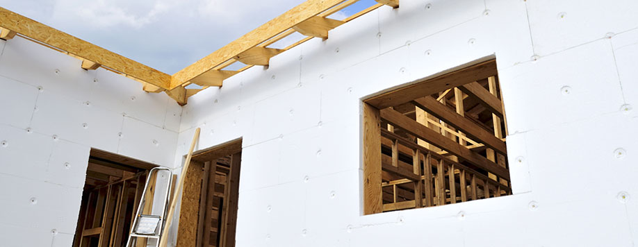
Rigid foam sheathing insulation is an innovative building and construction material that can significantly reduce a building’s energy use and help control indoor temperature. Gaps, holes and air leaks can make energy bills unnecessarily high and let valuable resources go to waste. High-performing foam insulation can help to effectively seal gaps and close air leaks, maintain indoor air temperature and reduce a building’s energy usage.
Rigid foams made with materials including polyisocyanurate (polyiso), extruded polystyrene (XPS) and expanded polystyrene (EPS) are valued for their insulating properties and offer durability, energy savings and moisture control. Following are examples of a variety of benefits that rigid foam insulation made from polyiso, XPS and EPS offer to the building environment, including:

Energy efficiency: According to the U.S. Department of Energy, heating and cooling accounts for approximately half of the energy used in a typical home in the United States. Foam insulation can help consumers lower their energy bills by reducing air leaks and by decreasing the transfer of heat between indoor and outdoor environments In addition, rigid foam building insulation materials save as much as 40 BTUs of energy for every BTU of energy consumed to make the material and can make a home up to 70 percent more energy efficient. Insulation materials made possible by these chemistries help save more than 200 times the energy needed to make them.
Moisture resistance: When moisture passes through the walls, it can increase mold and mildew in the building envelope. Properly installed rigid foam board provides a layer of protection against moisture.
Enhanced R-value: With a long-term R-value from 3 to 5 or higher per inch, rigid foam insulation boards can increase the R-value of the entire wall, covering wood studs and other parts of the wall, such as framing, ducts, wiring and plumbing. When properly installed, rigid foam board forms a complete air barrier that reduces air infiltration, the leading cause of energy loss.
Fire safety: Foam insulation manufacturers add flame retardants to their products to help prevent fires from starting, to limit the spread of fires and to minimize fire damage. Flame retardants in foam insulation are an important line of defense when it comes to fire safety. They can help protect building occupants and first responders from fire-related death and injury, and owners and occupants from property loss.